mond2020: Mit seiner Ankündigung vom Januar 2004 der NASA, das Budget für die Errichtung einer Basis auf dem Mond zu Verfügung zu stellen, hat US Präsident George W. Bush, damals wohl ungewollt, den Startschuss für ein erneutes Weltraumrennen gegeben??
Forty years ago today on Dec. 11, 1972, astronaut Eugene A. Cernan, commander, makes a short checkout of the lunar rover during the early part of the first Apollo 17 extravehicular activity at the Taurus-Littrow landing site. This view of the "stripped down" rover is prior to loading up. Equipment later loaded onto the rover included the ground-controlled television assembly, the lunar communications relay unit, hi-gain antenna, low-gain antenna, aft tool pallet, lunar tools and scientific gear.This photograph was taken by scientist-astronaut Harrison H. Schmitt, lunar module pilot. The mountain in the right background is the east end of South Massif. While astronauts Cernan and Schmitt descended in the Lunar Module "Challenger" to explore the moon, astronaut Ronald E. Evans, command module pilot, remained with the Command and Service Modules "America" in lunar orbit.
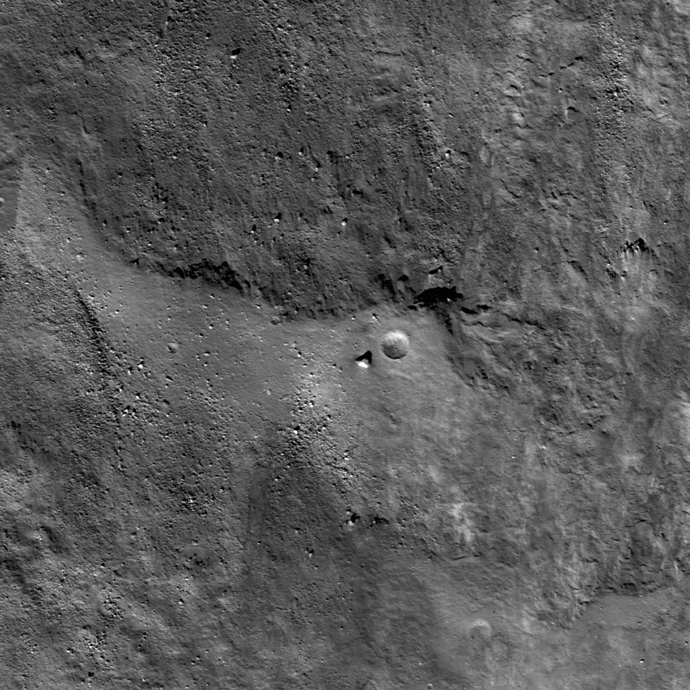
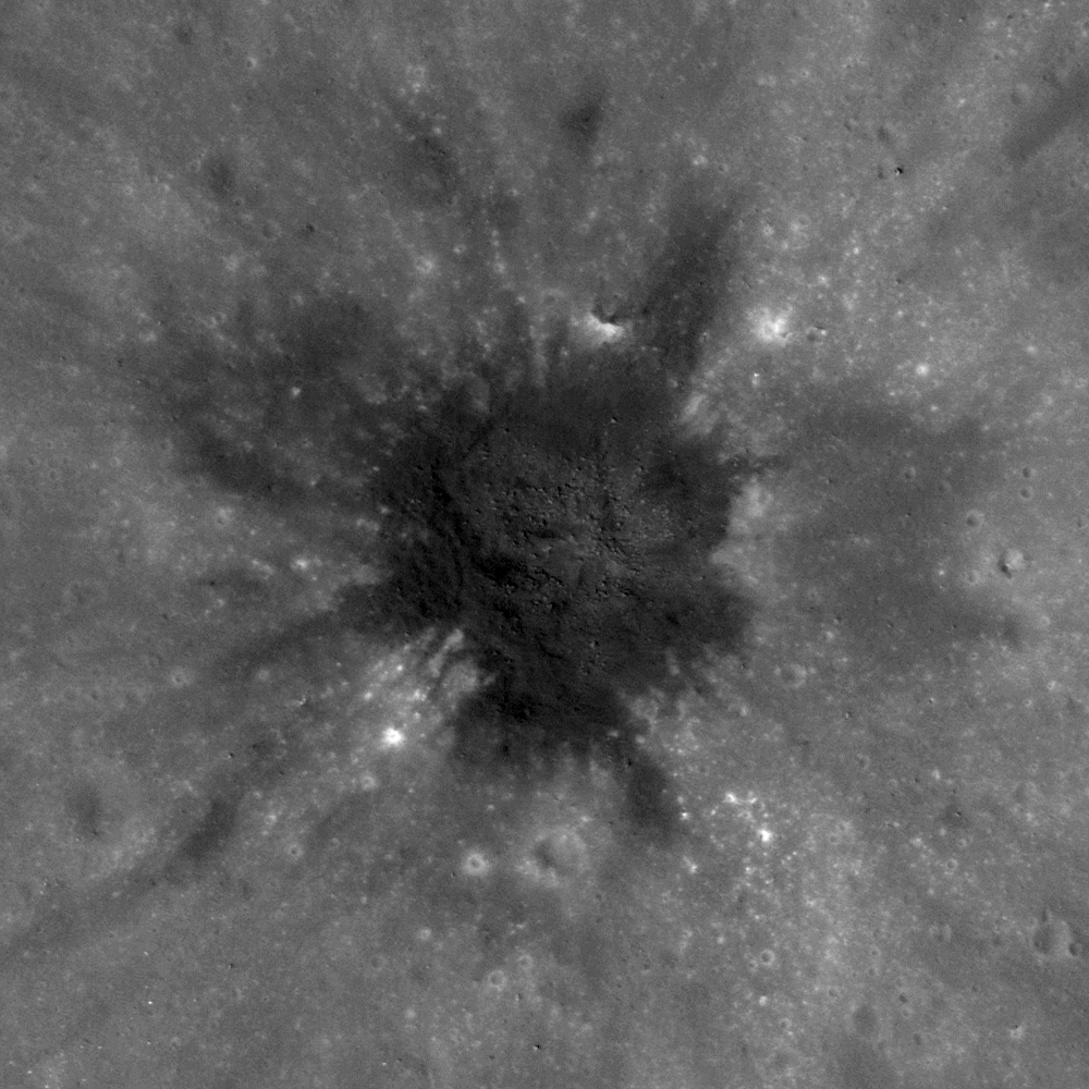
Explore the pyroclastics in the full LROC NAC frame, HERE!
An impact excavated low-reflectance pyroclastic formation, part of a landmark region of the Moon's nearside characterized by dark mantling deposits east of Copernicus. LROC Narrow Angle Camera (NAC) observation M170613335L,, LRO orbit 10277, September 14, 2011. Image field of view 418 meters, angle of incidence 13.03° at 0.49 meters resolution from 44.83 kilometers. View the larger 500 meter field of view in the LROC Featured Image HERE [NASA/GSFC/Arizona State University].
Lillian Ostrach
LROC News System
Some regions of the Moon exhibit dark mantling deposits that were formed by fire-fountain style eruptions, similar to Strombolian or some Hawaiian eruptions. Unlike the effusively emplaced mare basalts, pyroclastic eruptions were more energetic because the erupted material contained more volatiles and formed volcanic glass beads. In some cases, pyroclastics are found in small, localized areas, surrounding a vent such as in Alphonsus crater or in Schrödinger basin.
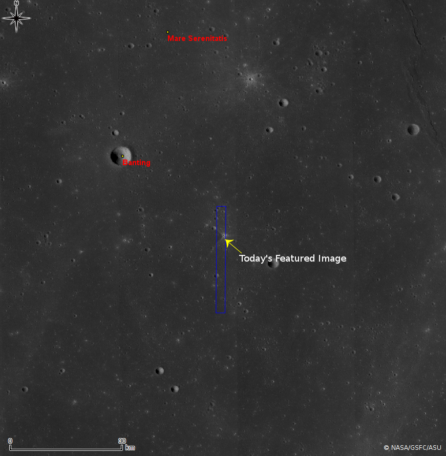
Today's Featured Image is located within a larger regional pyroclastic deposit (5.470°N, 352.014°E; low-reflectance material) south of Sinus Aestuum, and is centered on a small impact crater (~170 m diameter) that excavated fresh pyroclastic material from depth. Since this crater is located within a regional pyroclastic deposit, the freshly-exposed pyroclastics appear lower reflectance than the surrounding surface, possibly as a result of ejecta emplacement from impacts (both near and far afield) that deposited higher-reflectance material and mixed the regolith (impact gardening).
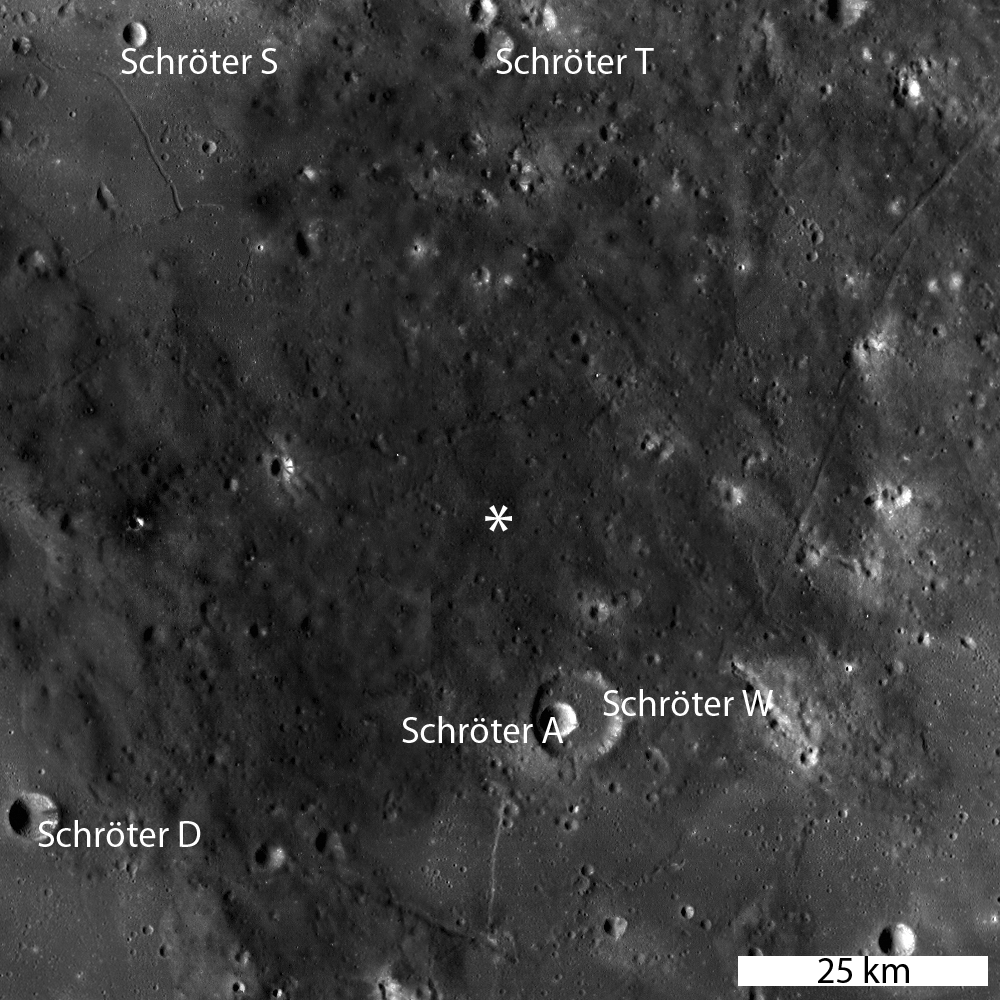
LROC Wide Angle Camera (WAC) monochrome mosaic centered on the regional pyroclastic deposits south of Sinus Aestuum and east of Copernicus. Asterisk notes
location of the field of view highlighted at high resolution in the LROC Featured Image released June 7, 2012. View the larger context image HERE [NASA/GSFC/Arizona State Universi
Understanding the distribution, extent, and thickness of pyroclastic deposits can help constrain the volcanic history of the Moon and answer questions regarding the volatile content of the early Moon. For example, Apollo 17 samples of pyroclastic glass from the Taurus-Littrow Valley confirmed that fire-fountain eruptions occurred on the Moon and that the glass beads were rich in titanium as well as small amounts of zinc and sulfur (volatiles). More recently, scientists have improved upon the measured values for volatiles, such as carbon dioxide, water, fluoride, sulfur, and chlorine, in the pyroclastic glasses returned from the Apollo missions. Isn't it amazing how much we can learn from the Apollo samples?
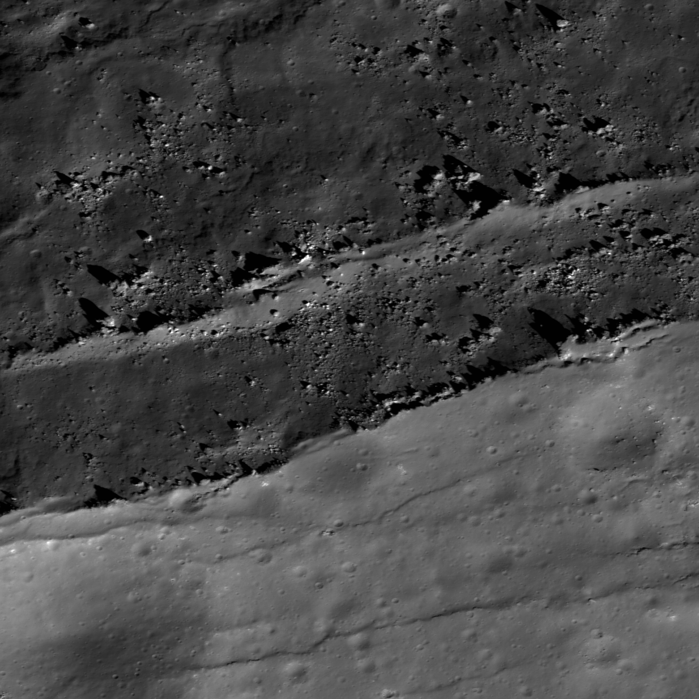
Summit of Tycho crater central peak seen from west-to-east; the rough material on the floor of the crater in the upper right formed as a massive pool of impact melt solidified. LROC NAC M181286769L,R
The same field of view at a slightly less inclined morning incidence angle (60.84°), LROC NAC M129452673R, orbit 4211, May 25, 2010, resolution 0.46 meters from 37.66 kilometers [NASA/GSFC/Arizona State University].
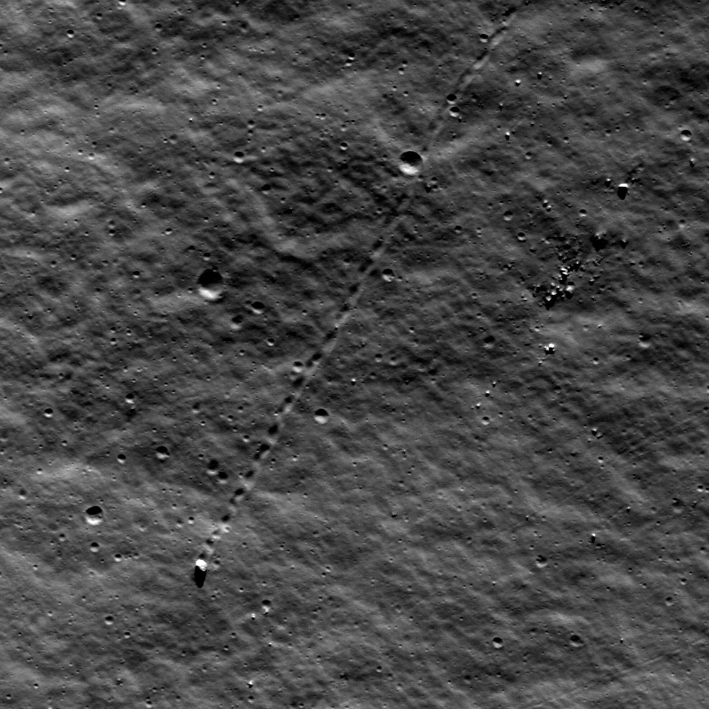
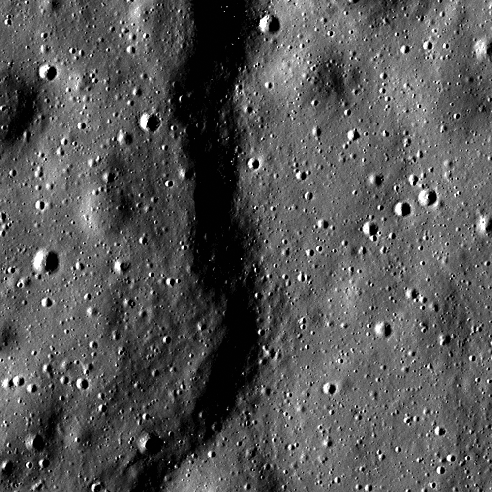
A small scarp is exposed in this high sunrise incidence angle (75.95°) Narrow Angle Camera frame, around 95 kilometers north by northeast of Mons La Hire in Mare Imbrium. The area to the east is raised relative to the area on the west of the scarp by as little as 10 meters. LROC NAC M177792062L, LRO orbit 11337, December 6, 2011; field of view 610 meters, resolution 0.6 meters per pixel from 43.86 kilometers. View the full-size LROC Featured Image HERE[NASA/GSFC/ArizonaState University].
Drew Enns
LROC News System
Today's Featured Image shows the boundary of a flow front in Mare Imbrium. Unlike other flows LROC has observed (granular, impact melt), these are lava flows! The flows are about 35 m thick, making them hard to observe unless the Sun is low and casting long shadows.
Apollo 15 imaged the flows early in the lunar morning, when the Sun was low on the horizon to help the low relief flows cast larger shadows!
Combining the observed geometric properties of these flows with viscosities calculated from the Apollo samples allow scientists to constrain how lava behaves on the Moon.
For context, the full, uncorrected approximate 2200 meter width of the field of view swept up in LROC NAC M129452673R. The area of interest is just left of center [NASA/GSFC/Arizona State University].
LROC Wide Angle Camera (WAC) context for the LROC Featured Image, released April 11, 2012 and narrowly focused near 30.593° N, 335.302° E. The WAC observation above was swept up from the orbiter during the same orbital pass as that of the Featured Image NAC frame. The large incidence angle brings out subtle changes in topography, enhancing the Imbrium lava flows. Image field of view is 35 kilometers. LROC WAC M177791761C (604nm), resolution 60 meters per pixel [NASA/GSFC/Arizona State University].
The Imbrium flows are fairly thick, and the WAC context shows them extending for at least 120 km, but the flows continue for several hundred kilometers. Should we expect this? Because the Moon's gravity is weaker than the Earth's, we can expect lunar lava flows to be ~1.7 times as thick as a terrestrial flow of similar length!
Flows of similar length on Earth have only been observed in flood basalts, which are large volumes of lava that were erupted quickly.
This correlation indicates that the lunar lava flows must have erupted quickly as well. Even so, these flows are some of the few examples still visible on the Moon's surface, and it is unclear how their thickness and extent relate to the majority of volcanism that filled in the large basins resulting in the maria.
Check out more lava related feature posts below and explore the lava flows in the full LROC NAC Featured Image, HERE.
NASA Great Moonbuggy Race is sponsored by
Lockheed Martin, Boeing, Northrop Grumman Corporation, and Jacobs ESTS Group.
Approximately 100 returning and rookie teams from around the world will
compete for a top-three finish at the 19th-annual NASA Great Moonbuggy
Race, April 13-14, at the U.S. Space and Rocket Center in Huntsville.
More than 500 high school, college and university students from 20
states, as well as Puerto Rico, Canada, Germany, Russia, United Arab
Emirates, Italy and India, are expected to race their specially crafted
lunar rovers or "moonbuggies."
A lasting lesson from Apollo. The lunar exosphere gets into everything, fine as talcum, abrasive as broken glass, and a significant cumulative threat to seals and any and all working parts generally, whether biological and mechanical. Beyond its demonstrated mission threat the Moon's dusty environment
is a delicate, "pristine" and important part of a 4.5 billion year
history of space weather near Earth. Apollo 17 lunar module pilot and
geologist Harrison H. "Jack" Schmitt moves forward with the patina of 22
hours activity on the lunar surface clinging to his suit. AS17-145-22157 [NASA/JSC/ALSJ].
The Moon's sodium tail,
Potter and Morgan (1998).
The Lunar Dust Environment:
Expectations for the LADEE
Lunar Dust Experiment (LDEX)
Mihaly Horanyi, Sternovsky & Shul
with Colette, Grün, Kempf, Srama & Mocker
43rd Lunar and Planetary Science Conference, #2635
Introduction: The lunar dust environment is expected to be dominated by submicron-sized dust particles released from the Moon due to the continual bombardment by micrometeoroids, and due to plasma-induced near-surface intense electric fields. The Lunar Dust EXperiment (LDEX) is designed to map the spatial and temporal variability of the dust size and density distributions in the lunar environment on-board the upcoming Lunar Atmosphere and Dust Environment Explorer (LADEE) mission
LDEX is an impact detector, capable of measuring the mass of submicron sized dust grains. LDEX will also measure the collective signal of dust grains below the detection threshold for single dust impacts; hence it can search for the putative population of grains with r ~ 0.1 μm lofted over the terminator regions by plasma effects.
LDEX has been developed at the Laboratory for Atmospheric and Space Physics and Colorado Center for Lunar Dust and Atmospheric Studies (LASP/CCLDAS, University of Colorado at Boulder) and has a high degree of heritage based on similar instruments on the HEOS 2, Ulysses, Galileo, and Cassini missions. The LDEX flight model will be tested and calibrated at both the (Max-Planck-Institute for Nuclear Physics, Heidelberg, Germany) and Boulder dust accelerator facilities.
At the Lunar and Planetary Science Conference, March 21, 2012, Dr. Horányi summarized expected capabilities of LDEX and made predictions for its measurements in lunar orbit, based on current theoretical models. The authors also discussed a proposed LDEXPLUS instrument being developed for a possible LADEE follow-up mission to add the instrument's design capability for in-situ chemical analysis of impacting dust particles, perhaps to verify "the existence of water ice on the lunar surface and map the density of valuable resources of commercial interest".
Figure 1. LDEX EM and FM units and the schematic drawings of the instrument.
The LDEX instrument: The two expected sources of dust in the lunar environment are ejecta production due to continual bombardment by interplanetary meteoroids and lofting due to plasma effects. LDEX is an impact ionization dust detector with a sensor area of ~0.01 m\2. LDEX is a low risk, compact instrument and uses no flight software (Figure 1). In addition to individual dust impacts of grains with radii r > 0.3 μm, LDEX can identify a large population of smaller grains (0.1 < r < 0.3 μm) by measuring their collective signal.The expected impact rates, and the signature of lofted small grains expected over the terminators are shown in Figure 2.
Figure 2. Expected impact rates on a 30x100 km orbit with its pericenter over the morning terminator.
Initial test and calibration of the LDEX FM model were done at the CCLDAS dust accelerator facility. Full calibrations are planned in early 2012 at both the Heidelberg and the Boulder facilities. Figure 3 shows the preliminary test results, indicating that LDEX will meet or exceed its measurement requirements.
Figure 3. Initial test results for the LDEX FM instrument showing the detected particle mass versus their velocity. At the expected impact speed of 1.6 km/s,
LDEX will detect particles with radii r > 0.4 μm. The ratio of detected and undetected particles matches the expected value due to the duty cycle of the electronics and the transparency of the screens that provide shielding and exclude the solar wind electrons from entering LDEX.
The LDEX-PLUS instrument extends the LDEX capabilities to also measure the chemical composition of the impacting particles with a mass resolution of M/ΔM > 30. Traditional methods to analyze surfaces of airless planetary objects from an orbiter are IR and gamma-ray spectroscopy, and neutron backscatter measurements. A complementary method is to analyze dust particles as samples of planetary objects from which they were released. The source region of each analyzed grain can be determined with accuracy at the surface that is approximately the altitude of the orbit.
This ‘dust spectrometer’ approach provides key chemical constraints for varying provinces on the lunar surfaces. LDEX-PLUS is of particular interest to verify from orbit the presence of water ice in the permanently shadowed lunar craters. LDEX-PLUS combines the impact detection capabilities of LDEX with a linear time-of-flight system, similar to the Cassini Cosmic Dust Analyzer (CDA) instrument. Figure 4 shows an example time-of-flight mass spectrum of an ice-bearing dust grain.
Figure 4. Spectrum of a water ice particle obtained at ~ 4 km/s impact speed by the Cassini CDA instrument in Saturn's E ring. The dominant peaks are mass lines of water cluster ions (H2O)nH+, generated upon impact of an ice-bearing particle.
Schematic of documented species of horizon glow, such as the famous mid-lunar night imagery captured by Surveyor 7 in 1968.
Conclusions. LDEX, on-board LADEE, is scheduled to launch in May 2013 and will be capable of mapping the density distributions of both the large ejecta particles and the collective signal of small lofted grains. LDEX-PLUS, on-board a follow-up lunar mission, can collect a large number of samples from a greater part of the entire surface for analysis.
The instrument is especially sensitive to the metallic compounds of minerals and any species which easily form ions (e.g. water). The accuracy of the trajectory back-tracing to the surface is comparable to the altitude of the satellite. This in-situ method allows compositional surface mapping of the Moon. Since the dust spectrometer is particularly sensitive to refractory compounds which are difficult to access by other methods it is also complementary to remote sensing spectroscopy and an ion or neutral mass spectrometer. A ram pointing dust spectrometer and a nadir pointing remote sensing instrument collect data from approximately the same spot on the surface of the Moon, hence the combination of these measurements greatly enhances our ability to map the chemical composition of the surface and identify water-bearing regions.
An LDEX-PLUS type instrument can also address many of the science goals of a Europa Jupiter System Mission (EJSM) regarding the surface chemistry of icy satellites. See original Conference abstract, HERE, for citations.
Lunar Horizon Glow (LHC) as televised (vidicon photography) in local night, early 1968 [NASA].
The 'Dust, Atmosphere, and Plasma: Moon and Small Bodies' (DAP-2012) meeting will take place in Boulder, June 6-8, 2012. Please visit our webpages http://ldap2012.colorado.edu/ to register and submit an abstract by 3/30/2012, if you plan to attend.
We are looking forward to see you in Boulder!
- Alan Stern and Mihaly Horanyi
Lunar Pioneer, LLP
Quelle: |The Lunar Century Group News Traffic via Lunar Networks http://lunarnetworks.blogspot.com
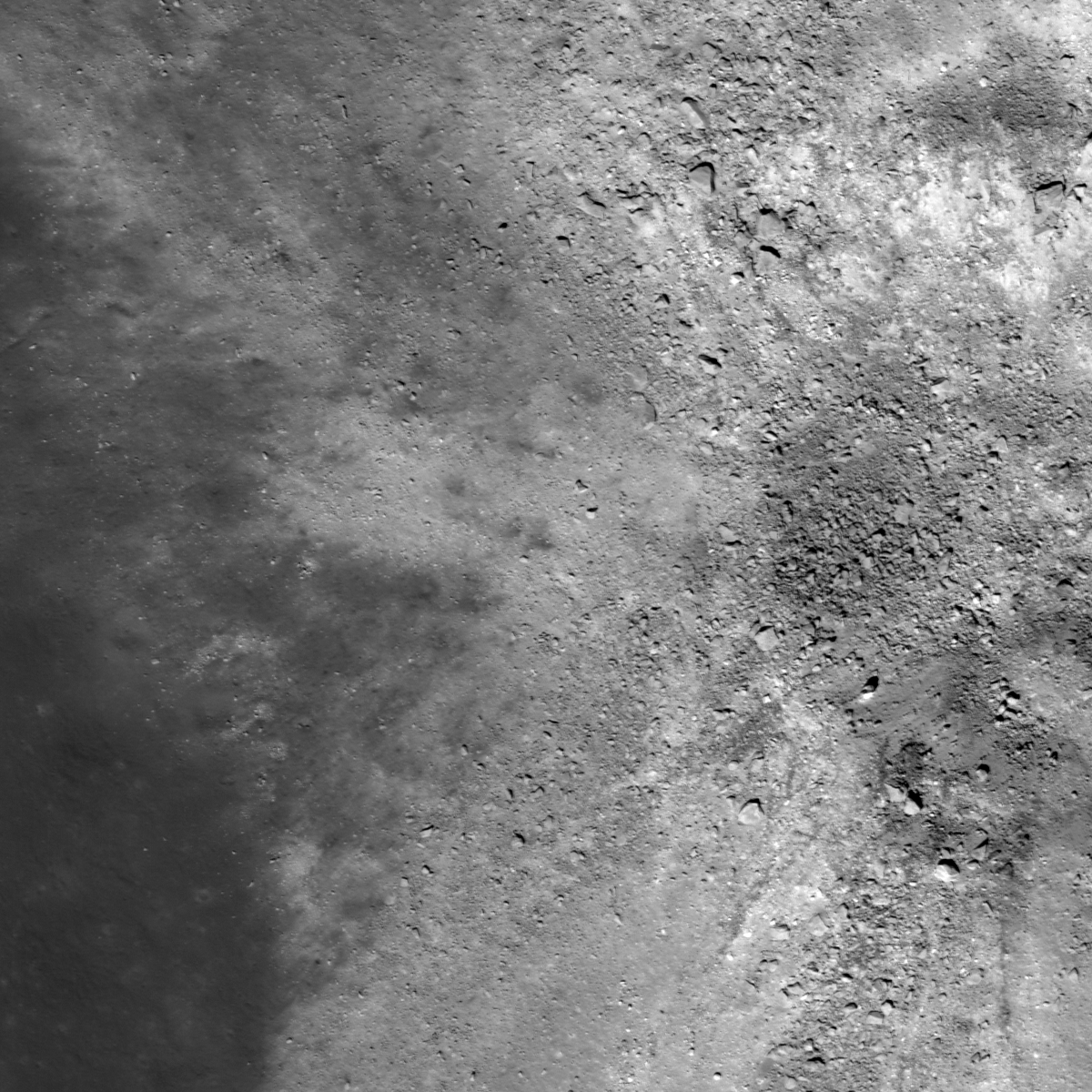
A large boulder stopped on its way down a sloping wall in the central peak complex of Schiller crater (51.8°S, 40.0°W). Illumination from the north, image is ~500 m across, NAC M109502471L
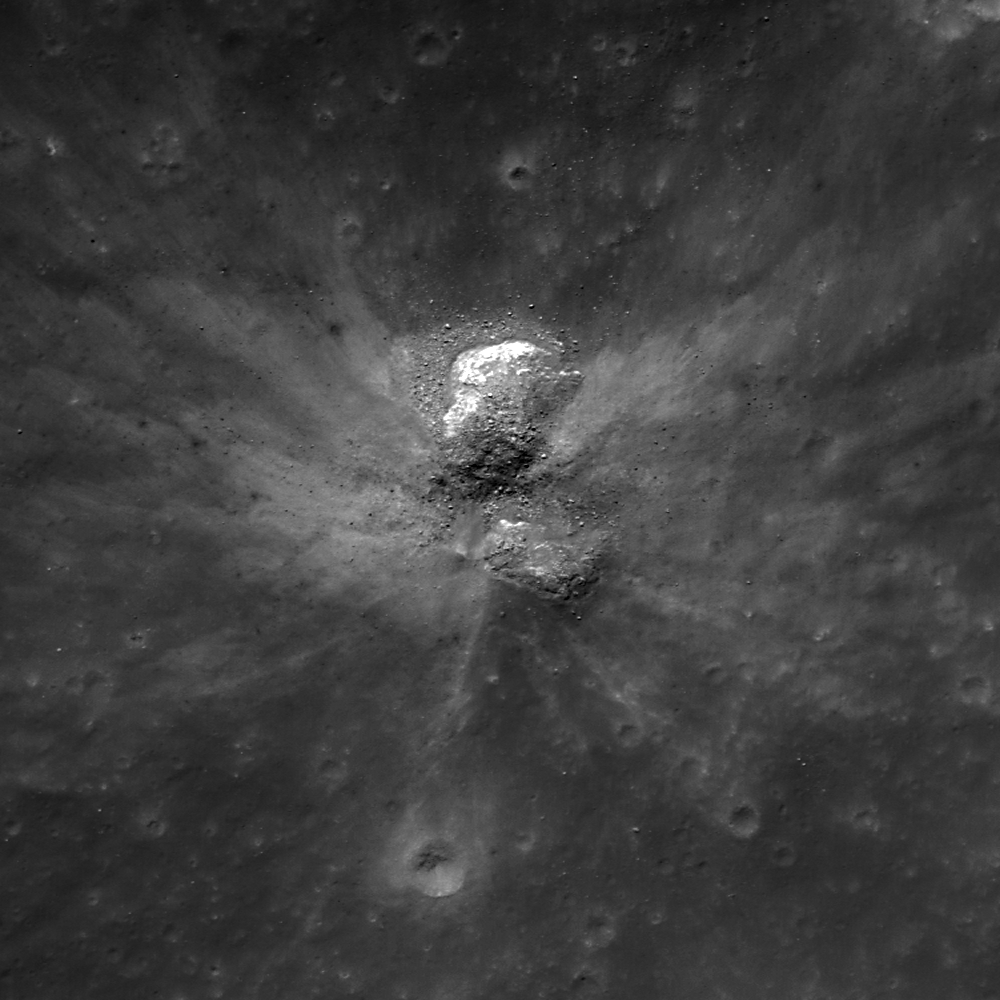
Western half of an unusual unnamed crater and its ejecta near the center of Mare Serenitatis. LROC Narrow Angle Camera (NAC) observation M139795376L, LRO orbit 5735, September 22, 2010; field of view 600 meters, incidence angle 28° from an altitude of 43.91 kilometers. View the full size LROC Featured Image HERE [NASA/GSFC/Arizona State University].
In many cases crater ejecta patterns on the Moon result in natural art.
Unlike the ejecta on the Earth and Mars, ejecta on th Moon does not interact with an atmosphere.
Thus the final pattern on the ground is solely a reflection the dynamics of impact cratering. Today's Featured Image highlights the western half of an unnamed crater located in the middle of Mare Serenitatis. The crater diameter is about 470 meters.
Context view of today's Featured Image, showing a wider view of the unnamed crater ejecta. Field of view close to the full 2.2 kilometer width of LROC NAC frame M139795376L. See the larger context image accompanying the image release HERE [NASA/GSFC/Arizona State University].
As seen in the second picture (a zoom-out of the same NAC frame), one third of the ejecta blanket (the western portion) is missing, probably due to an oblique impact from west to east. In the top image (near the crater center), almost all of the boulders are ejected in the northwest and southwest direction. The fine particles, however, extend out to the west in patterns not unlike a delicate lace. Studying the full variety of craters with distinctive ejecta patterns is key to understanding the dynamics of oblique impact events.
LROC Wide Angle Camera (WAC) 100 meter per-pixel monochrome mosaic of the center of the Mare Serenitatis basin. The yellow arrow and blue square show the location of the LROC Featured Image and the full NAC observation's footprint. See the larger WAC context image HERE[NASA/GSFC/Arizona State University].
Another very familiar crater famous for its asymmetric ejecta and as a nearside landmark of the Moon in an evening sky is bright Proclus - with lighthouse rays guarding "the gates" separating distinctive Palus Somni from Mare Crisium. View of the crater from Earth on March 29, 2010 from a spectacular full lunar disk mosaic by Astronominsk compared with LRO Nominal Mission LROC WAC image [Aстроноmинск (Луна) - NASA/GSFC/Arizona State University].
GRAIL auf dem Weg zum Mond ========================
Am 10. September startete eine Delta-II Rakete mit den beiden Zwillingssonden GRAIL-A und –B an Bord in Richtung Mond.
The Gravity Recovery and Interior Laboratory mission will create the most accurate gravitational map of the moon to date.
Hier kurz vor dem Start:
Nach zweitägiger Verspätung wie vorgesehen, verlief nun alles reibungslos und perfekt auch das Wetter spielte jetzt mit!
"Ein Wundervoller Tag zum Starten"lautete es aus dem NASA-Kontrollzentrum. quelle: nasan.gov
Last week we learned about the configuration of the Lunar Module (LM)
and discussed the landing operation in a “sequence of events” narrative.
This week we will review a few key control systems on the Lunar Module and the landing operations. Then we will discuss the maneuvers performed to land safely and softly on the lunar surface. This will help us understand how the astronauts controlled the LM. The LM has two main propulsion engines located on the Descent and Ascent stages. The LM also has four reaction control thruster assemblies located on the ascent stage to reorient (or point) the main engines in the proper direction. These thrusters are called attitude thrusters because they are used to point the craft in the proper direction or place it in the right ‘attitude'. Thruster firings to achieve the proper attitude are often called reorientation or attitude maneuvers. The proper attitude is very important to ensure that the large main engines apply their thrust vector (to change the orbital velocity) in the proper direction. This type of a burn is called a “delta velocity” (or delta-v) maneuver. In the Apollo missions the descent engine was pointed into the direction of travel (or the velocity vector) to perform a “retro” burn. The 30 second ‘Descent Orbit Insertion’ (DOI) burn reduces the craft’s velocity and lowers the LM's perilune (point closest to the Moon) to within about 50,000 feet (15 km) of the surface, about 260 nautical miles (480 km) up-range of the landing site.
At this point, the main engine was started again for ‘Powered Descent Initiation’ (PDI). During this time the crew flew on their backs, depending on the computer to slow the craft's forward and vertical velocity to near zero. Control was exercised with a combination of main engine throttling and attitude thrusters, guided by the computer with the aid of landing radar (LR). During the ‘braking phase’, the altitude decreased to approximately 10,000 feet (3.0 km), and the ‘final approach phase’ took the craft to approximately 700 feet (210 m). During final approach, the vehicle pitched over to a near-vertical position, allowing the crew to look forward and down to see the lunar surface for the first time.
The ‘landing phase’ began approximately 2,000 feet (0.61 km) up-range of the targeted landing site. At this point manual control was enabled for the Commander, and enough fuel reserve was allocated to allow approximately two minutes of hover time to survey where the computer was taking the craft and make any necessary corrections. (If necessary, landing could have been aborted at almost any time by jettisoning the descent stage and firing the ascent engine to climb back into orbit for an emergency return to the CSM.) Finally, three-foot-long probes extending from three footpads of the LM touched the surface, activating the ‘contact light’ that signals time for descent engine cutoff and allowing the LM to ‘touchdown’ softly onto the surface of the Moon.
Maneuvering the Lunar Lander
The maneuvers performed by the Lunar Module (LM) were DOI-2 (Descent Orbit Insertion #2), PDI (Powered Descent Initiation) and Landing maneuvers. DOI was a maneuver to insert the spacecraft in the correct orbit from which to initiate descent. DOI-1 was performed by the CSM with the LM still docked. The LM, using its RCS thrusters, performed DOI-2. PDI was the maneuver that brakes the LM out of lunar orbit and lands it softly on the surface of the Moon. This was the only maneuver to use the main engine of the Descent Propulsion System (DPS).
The DPS engine was ignited at 10% throttle and held there for 26 seconds to allow the DPS engine gimbal to be aligned through the spacecraft center of gravity before throttling up to maximum thrust. The braking phase was designed for efficient reduction of orbit velocity and, therefore, used maximum thrust for most of the phase; however, the DPS was throttled during the final two minutes of this phase. The DPS was able to be throttled only between 10% and 60%.
The approach phase provided visual monitoring of the approach to the lunar surface. At 'high gate' (from old aircraft-pilot parlance meaning the beginning of the approach to an airport in a landing path) the LM pitched forward to give the command pilot a view of the moon. 'Low gate' was the start of the landing phase, and was the point for making a visual assessment of the landing site to select either automatic or manual control. The entire sequence took about 12 minutes with only about two minutes for the astronauts to manually make any corrections to land the LM safely on the Moon.
Remember last week’s blog post when Neil Armstrong almost ran out of fuel landing the LM on the Moon!
The historic landing of Apollo 11 is a great human accomplishment that provided many pioneering experiences and ‘lessons learned’. After the great success of Apollo 11, NASA's next step was honing the Lunar Module's (LM) ability to make a pinpoint landing. Many of the future landing sites corresponded to areas with rough topography; the LM would have to come in steeply and set down within a few hundred meters of a designated point. The next Apollo mission used the lessons learned from the Apollo 11 lunar landing to demonstrate ‘pin-point’ landing capability, as well as the tremendous value of teamwork. Let’s listen to the great team effort of Commander Pete Conrad and Lunar Module Pilot Alan Bean as they land the Apollo 12 LM on the Moon with “loads of gas ... plenty of gas, plenty of gas” and “got it made” pinpoint accuracy. Listen for the call outs of key events and operational parameters such as the ‘pitch over’ maneuver and the constant monitoring of the altitude (feet), fuel remaining (%), LPD angle (degrees), and velocity (fps):
Apollo 12 - Approach and Landing - November 19, 1969
Why did the Apollo 12 lunar landing need to be so precise? (Hint: Rocks and soil were not the only things that the astronauts took back to the Earth to be analyzed – the answer will be published in the next blog post)
Simulators are often used to validate operational procedures and ‘practice’ maneuver execution skills, especially in a team environment. Control of the thrust vector is key to both the landing and the simulation. A series of throttle settings and pitch angles must be derived to guide the LM to a successful landing. The following is an example showing how the LM pitched forward and the engine was throttled back during the approach (visibility) and landing phases of a mission. This is just a generic diagram and is not specific to any particular mission. The pitch angles, thrust settings, velocities, altitudes and distances shown may be different for each mission.
The Commander (CDR) looks through a set of scribed marks on his window to assist him while the LM pilot gives him the Landing Point Designator (LPD) angle from the guidance computer. The LPD angle will tell him where to look along the vertical scale to find the place where the computer thinks they are going to land. If the CDR doesn't like the spot, he can move his hand-controller to tell the computer that he wants to change the landing spot up or back or to either side. A single movement of the hand-controller, which moves the landing point by a half degree or so, is usually referred to by the astronauts as a 'click'.
Here is a simulation of the “OUTSTANDING” teamwork of the Apollo 12 Lunar Landing crew:
Did you notice the set of LPD angle marks scribed on Commander Pete Conrad’s window to help him control the flight and the engine throttle while the LM Pilot kept the CDR informed of the systems' status and navigational information? Why is it important to have an initial visual landmark (like a crater)? Did you hear Alan Bean’s continuous communication of the key landing parameters that the Commander needed to control the landing – altitude (feet), fuel remaining (percentage), LPD angle (degrees), and velocity (fps)? Did you notice how the key parameters changed during the descent phases? Why is it important to watch for the dust? Did you hear the call for ‘contact light’, ‘engine off’ and other key operational events? What is a safe velocity (fps) to softly land the LM? We heard the three most important tools of teamwork ... Communication, Communication, and Communication!!!
Now for the FUN!
Curiosity is a sign of a healthy mind – as long as it is limited by good sense. But have you ever seen something and then try to do it yourself because you thought 'it can’t be that hard, in fact it looks so easy!' Well, as Murphy’s Law proves time and time again … nothing is as easy as it seems. There is always something that can come up as the 'surprise' element or the unexpected detail (like the 1202 alarms on Apollo 11). However, once you start practicing and doing something over and over again, you may encounter just about all of those unforeseen events that could eventually go wrong. Through practice we learn to understand the range of unanticipated (or anomalous) situations that can occur, thereby, acquiring valuable 'hands on' experience. This is the power of accurate simulators as a learning tool.
Next it’s your turn. Here is a simulation that you can use to practice your lunar landing skills. This classic video game accurately simulates the real motion of the lunar lander with the correct mass, thrust, fuel consumption rate, and lunar gravity. Its ‘dashboard’ display provides the critical operational parameters you need to monitor while executing landing phase maneuvers. The dashboard also provides the craft’s altitude (meters), range (meters), horizontal (v_x) and vertical (v_y) components of the velocity vector (mps), fuel gauge (kg) and thrust (N). During the simulation, the main engine thrust is graphically represented. At the top of the dashboard is an arrow that indicates the craft’s inertial pointing alignment through the spacecraft's center of gravity and thrust vector. You can enable/disable both the ‘Sound’ and ‘Vectors’ options in the simulation. The ‘Vectors’ option illustrate both the magnitude (size) and direction of the velocity and acceleration vectors. The simulation also provides the necessary keyboard manual control keys to fire ('click') the main descent engine and attitude thrusters (to ‘tilt’ the craft). Make sure to read the instructions including those in the ‘Help/Pause’ button. In addition, there is a ‘Reset’ button so you can practice, practice, practice...
Can you avoid the boulder field and land safely, just before your fuel runs out, as Neil Armstrong did in 1969? Can you ‘reorient’ (or tilt) the LM by using the attitude thrusters? What happens when you apply the thrust in different directions? Make sure to monitor both the x and y components of the velocity vector. Note the difference between the velocity and acceleration vectors as you fire the engine (apply thrust). At an altitude of 50 meters, can you ‘scoot across’ the surface to find a smooth surface to safely land like Neil Armstrong? Can you make a pinpoint landing like Apollo 12? How close can you come to the designated landing site (note the starting range of 45 meters)? How many points can you accumulate before you run out of fuel? How many soft landings can you perform? How about hard landings? How many ‘man-made’ craters did you create? The real lunar lander is very hard to control too. Good Luck and have Fun!
You can send us your best scores to magic@kelvin.net and we will publish it on the blog post or just leave a comment below to let us know what you learned and how well you did.
Hope you have lots of FUN!
Mystical Moon
'All one can really leave one's children is what's inside their heads. Education, in other words, and not earthly possessions, is the ultimate legacy, the only thing that cannot be taken away.' - Dr. Wernher von Braun
Let’s learn a little about Lunar Landing. This is the first week of a two part blog posting about landing on the lunar surface. In an earlier blog post we learned about the turbulent history of the surface of the Moon scarred by craters caused by meteorite impacts. Well, meteorites weren’t the only objects to impact the lunar surface. In fact, early human exploration of the Moon also included many “impact” missions to the Moon. The first lunar exploration vehicles of the 1950s were primitive pioneers. However, technology developed so rapidly that only about a decade separated the first flyby forays and Neil Armstrong's history-making steps on the Moon's surface.
It started in January 1959, when a small Soviet sphere named Luna 1 flew by the Moon at a distance of some 3,725 miles (5,995 kilometers). Though Luna 1 did not impact the Moon's surface, as was likely intended, its suite of scientific equipment revealed for the first time that the Moon had no magnetic field. The craft also returned evidence of space phenomena, such as the steady flow of ionized plasma now known as solar wind.
First Lunar Landings (or Impacts)
Later in 1959 Luna 2 became the first spacecraft to land on the Moon's surface when it impacted near the Aristides, Archimedes, and Autolycus craters. A third Luna mission subsequently captured the first blurry images of the far side of the Moon.
In 1962 NASA placed its first spacecraft on the Moon — Ranger 4. The Ranger missions were ‘kamikaze’ missions; the spacecraft were engineered to streak straight toward the Moon and capture as many images as possible before crashing into its molten core. Unfortunately Ranger 4 was unable to return any scientific data before slamming into the far side of the Moon. Two years later, however, Ranger 7 streaked toward the Moon with camera shutters snapping and captured more than 4,000 photos in the 17 minutes before it smashed onto the surface. Images from all the Ranger missions, particularly Ranger 9, showed that the Moon's surface was covered with craters. The photos highlighted the challenges of finding a smooth landing site on the Moon’s surface.
In 1966 the Soviet spacecraft Luna 9 overcame the Moon's topographic hurdles and became the first vehicle to soft-land safely on the surface. The small craft was stocked with scientific and communications equipment and photographed a ground level lunar panorama. Luna 10 launched later that year and became the first spacecraft to successfully orbit the Moon.
The Surveyor space probes (1966-68) were the first NASA crafts to perform controlled landings on the Moon's surface. Surveyor carried cameras to explore the Moon's surface terrain, as well as soil samplers that analyzed the nature of lunar rock and dirt (regolith). In 1966 and 1967 NASA launched lunar orbiters that were designed to circle the Moon and chart its surface in preparation for future manned landings. In total, five lunar orbiter missions photographed about 99 percent of the Moon's surface.
Man on the Moon
These robotic probes paved the way for a giant leap forward in space exploration. On July 20, 1969, Neil Armstrong and Edwin 'Buzz' Aldrin became the first humans to reach the Moon when their Apollo 11 lunar lander touched down in the Sea of Tranquility. Later Apollo missions carried a lunar rover that was driven across the satellite's surface, as astronauts spent as long as three days on the Moon. Five other missions and a dozen men had visited the Moon before the Apollo project ended in 1972.
After the dramatic successes of the 1960s and 1970s, the major space programs turned their attention elsewhere for a few decades. But in 1994, NASA again focused on the Moon. The Clementine mission succeeded in mapping the Moon's surface in wavelengths other than visible light, from ultraviolet to infrared. Later, the Lunar Prospector (1999) orbited the Moon in search of possible evidence of ice at the lunar poles. The prospector also explored the Moon's gravitational field and remapped its surface. The mission's end was spectacular—the craft was intentionally crashed into the Moon in the hopes of raising a plume that could yield evidence of water ice, but none was observed.
Recently, NASA deliberately crashed an upper Centaur stage and the ‘shepparding’ spacecraft into the surface of the Moon. The mission objectives of the Lunar Crater Observation and Sensing Satellite (LCROSS) include confirming the presence (or absence) of water ice in a permanently shadowed crater at the Moon’s South Pole. In 2009, LCROSS excavated the permanently dark floor of one of the Moon’s polar craters (Cabeus) to test the theory that ancient ice lies buried there. Moving at a speed of more than 1.5 miles per second, the Centaur upper stage hit the lunar surface shortly after 4:31 a.m. PDT on October 9, 2009, creating an impact that instruments aboard LCROSS observed for approximately four minutes. The impact ejected material from the crater’s floor to create a plume that the specialized instruments were able to analyze for the presence of water (ice and vapor), hydrocarbons and hydrated materials. LCROSS then impacted the surface at approximately 4:36 a.m. PDT. The mission accomplished its objectives by revealing the presence of water from yet another successful lunar impacting mission. I guess we can say that the LCROSS mission created a crater within a crater inside the Cabeus crater. So, it’s pretty fair to say that there are quite a few ‘man-made’ craters on the Moon too.
Now let’s look at a few famous ‘soft landings’ on the surface of the Moon and how they were accomplished.
The Apollo Lunar Landers
The Lunar Module was originally designated the Lunar Excursion Module or LEM. Over the course of its development, the name was officially changed to Lunar Module (LM), eliminating the word 'excursion'. This was done because NASA was pushing to get funding for some kind of powered lunar surface mobility and they wanted to make it clear that such 'excursions' were beyond the capabilities of the lunar lander itself. (This new excursion capability was eventually realized with the Lunar Rover.) After the name change from 'LEM' to 'LM', the pronunciation of the abbreviation did not change, as the habit became ingrained among engineers, astronauts, and the media to universally pronounce 'LM' as 'LEM' which is easier than saying the letters individually.
The Apollo Lunar Module (LM) was the ‘Lander’ portion of the Apollo Moon missions built to carry a crew of two from lunar orbit to the surface and back. Six such crafts successfully landed on the Moon from 1969 to 1972. The LM, consisting of an Ascent stage and Descent stage, was ferried to lunar orbit by its companion Command/Service Module, a separate spacecraft of approximately twice its mass, which took the astronauts back home to Earth. After completing its mission, the LM was discarded.'
Here is a short video describing the design of the “LEM”:
At launch, the Lunar Module sat directly beneath the Command/Service Module (CSM) with legs folded, inside the Spacecraft-to-LM Adapter (SLA) attached to the S-IVB third stage of the Saturn V rocket. There it remained through Earth parking orbit and the Trans Lunar Injection (TLI) rocket burn to send the craft toward the Moon. Soon after TLI, the SLA opened and the CSM separated, turned around, came back to dock with the Lunar Module, and extracted it from the S-IVB. During the flight to the Moon, the docking hatches were opened and the LM Pilot entered the LM to temporarily power up and test its subsystems (except for propulsion). Throughout the flight, he performed the role of an engineering officer, responsible for monitoring the systems of both spacecraft.
After achieving a lunar parking orbit, the Commander and LM Pilot entered and powered up the LM, replaced the hatches and docking equipment, unfolded and locked its landing legs, and separated from the CSM. Flying independently, the Commander operated the flight controls and engine throttle, while the Lunar Module Pilot operated other spacecraft systems and kept the Commander informed on systems status and navigational information. After inspection of the landing gear by the Command Module Pilot, the LM was withdrawn to a safe distance, then the descent engine was pointed forward into the direction of travel to perform the 30 second ‘Descent Orbit Insertion’ burn to reduce speed and drop the LM's perilune (point closest to the Moon) to within approximately 50,000 feet (15 km) of the surface, about 260 nautical miles (480 km) up-range of the landing site.
At this point, the engine was started again for ‘Powered Descent Initiation’. During this time the crew flew on their backs, depending on the computer to slow the craft's forward and vertical velocity to near zero. Control was exercised with a combination of engine throttling and attitude thrusters, guided by the computer with the aid of landing radar. During the ‘braking phase’, the altitude decreased to approximately 10,000 feet (3.0 km), and then the ‘final approach phase’ went to approximately 700 feet (210 m). During final approach, the vehicle pitched over to a near-vertical position, allowing the crew to look forward and down to see the lunar surface for the first time.
The ‘landing phase’ began approximately 2,000 feet (0.61 km) up-range of the targeted landing site. At this point manual control was enabled for the Commander and enough fuel reserve was allocated to allow approximately two minutes of hover time to survey where the computer was taking the craft and make any necessary corrections. (If necessary, landing could have been aborted at almost any time by jettisoning the descent stage and firing the ascent engine to climb back into orbit for an emergency return to the CSM.) Finally, three-foot-long probes extending from three footpads of the lander touched the surface, activating the ‘contact indicator light’ which signals time for descent engine cutoff, allowing the LM to settle softly on the surface.
When ready to leave the Moon, the LM would separate the descent stage and fire the ascent engine to climb back into orbit, using the descent stage as a launch platform. After a few course correction burns, the LM would rendezvous with the CSM and dock for transfer of the crew and rock samples. Having completed its job, the LM was separated and sent into solar orbit or to crash into the Moon.
Let’s watch a simulation of the Apollo Lunar Landing sequence described above. Note the RCS (reaction control system) thrusters on the LM fire to ‘reorient’ the craft into the proper ‘attitude’ (pointing direction) for the ‘Descent Orbit Insertion’ burn:
Now let’s look at a video of the true story of the first humans, Neil Armstrong and “Buzz” Aldrin, landing the Lunar Module on the surface of the Moon. Listen for the astronaut call-out of the illumination of the 'contact light' and 'engine stopped':
Phew, that was a close one – they almost ran out of fuel! Next week we will continue this blog post with Part 2. Please join us again - we promise that you will have FUN!
See you next week!
Mystical Moon
'All one can really leave one's children is what's inside their heads. Education, in other words, and not earthly possessions, is the ultimate legacy, the only thing that cannot be taken away.' - Dr. Wernher von Braun
Image:Cape Canaveral, Fla. The two Grail spacecraft (Grail-A and Grail-B)
made the trip from the Denver area to the Shuttle Landing Strip at the
Kennedy Space Center, Fla. on May 20, 2011.
Two NASA spacecraft with a date for lunar orbit early next year have arrived in Florida to prepare for a launch in September.


